To start, I had to figure out a way to trigger the camera to take a picture. Fortunately, there is a port on the side of Canon cameras to attach a shutter release cable (image below adapted from Canon 6D manual).
To start, I had to figure out a way to trigger the camera to take a picture. Fortunately, there is a port on the side of Canon cameras to attach a shutter release cable (image below adapted from Canon 6D manual).
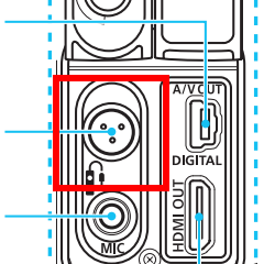
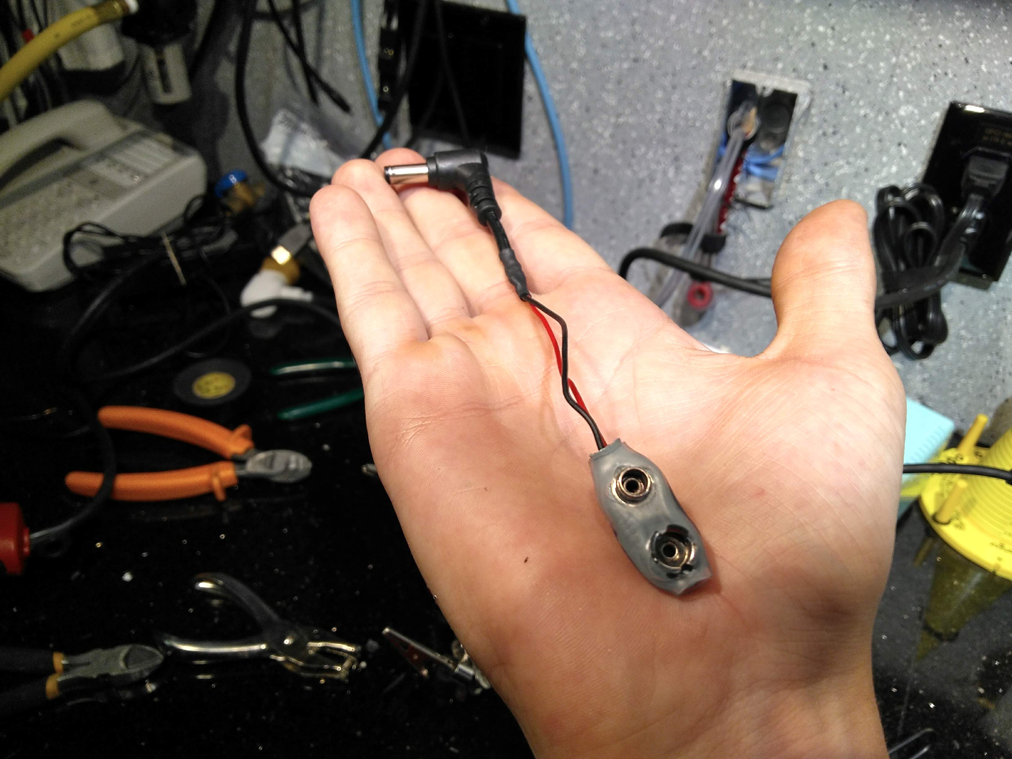
These cables are usually attached to a remote that you can use to take a photo, which helps to prevent camera shake. I wanted to be able to use this port to trigger the camera with an Arduino, which isn't very common, so I had to make my own cable. This port is a funny shape, so I had to buy a cheap shutter release cable on Amazon which I could cut the port off of. First, I took the remote apart so I could figure out which wire did what.
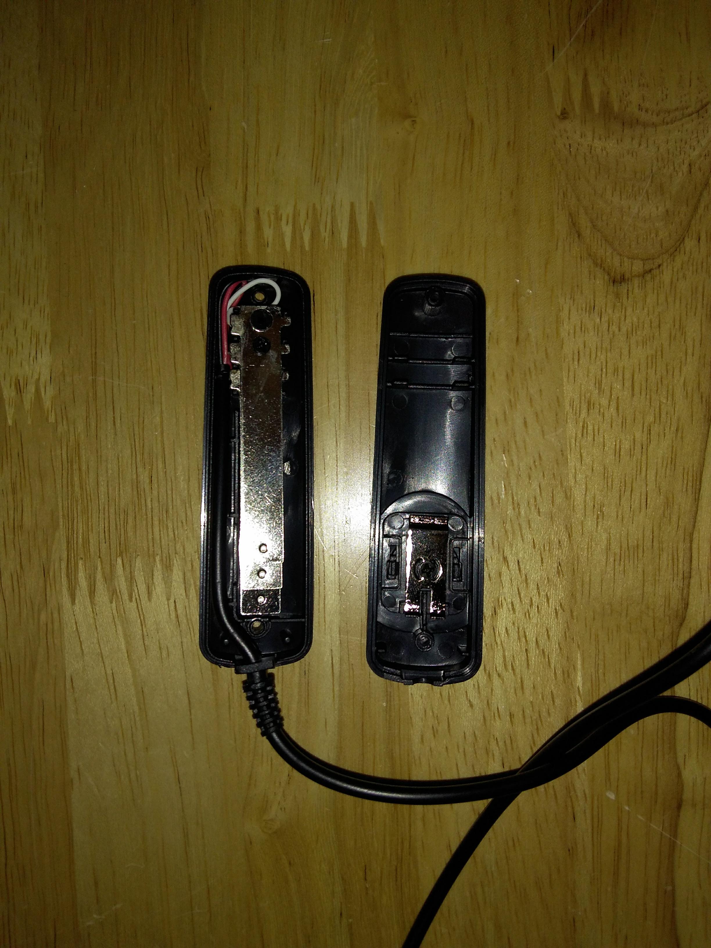
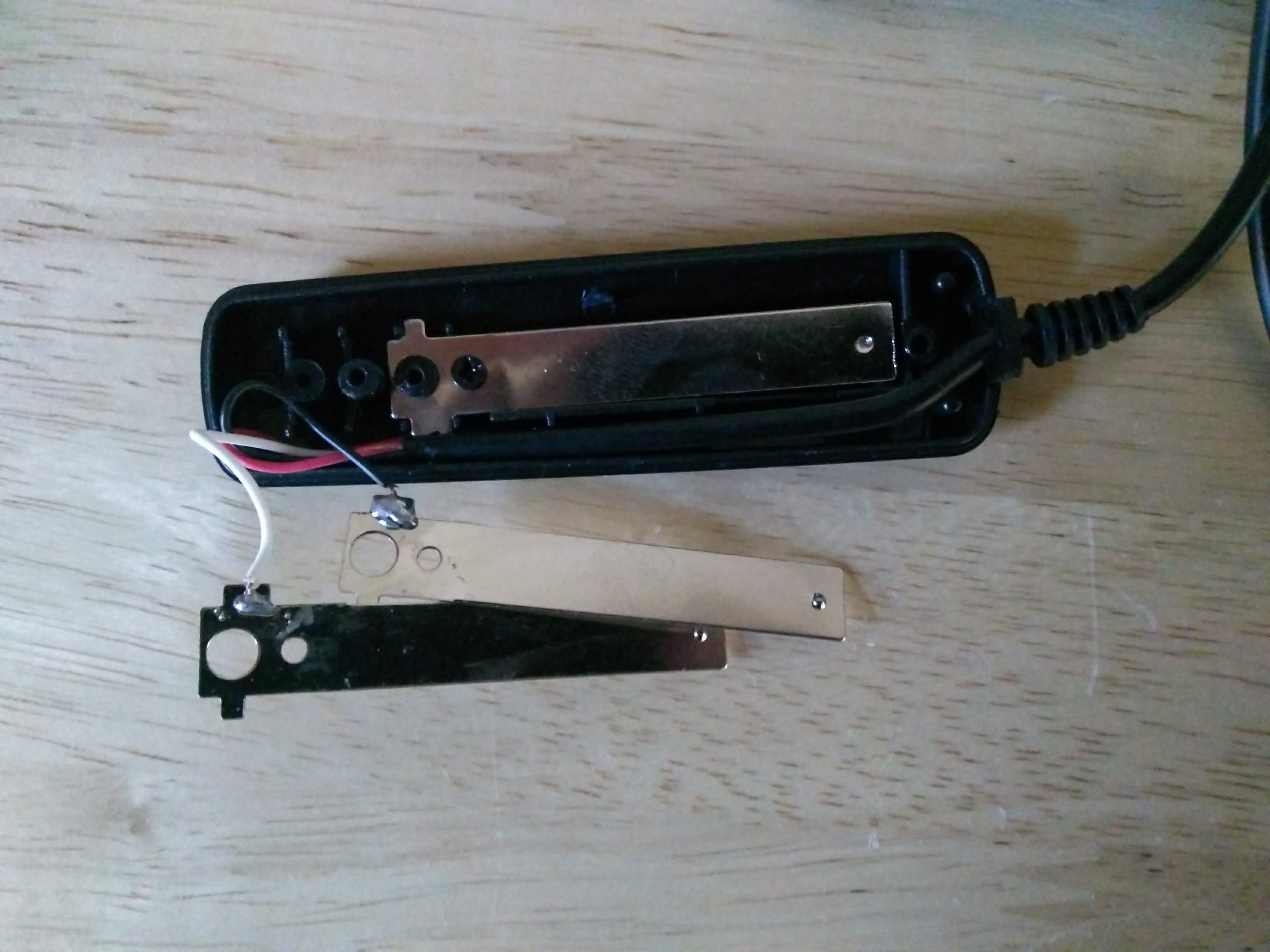
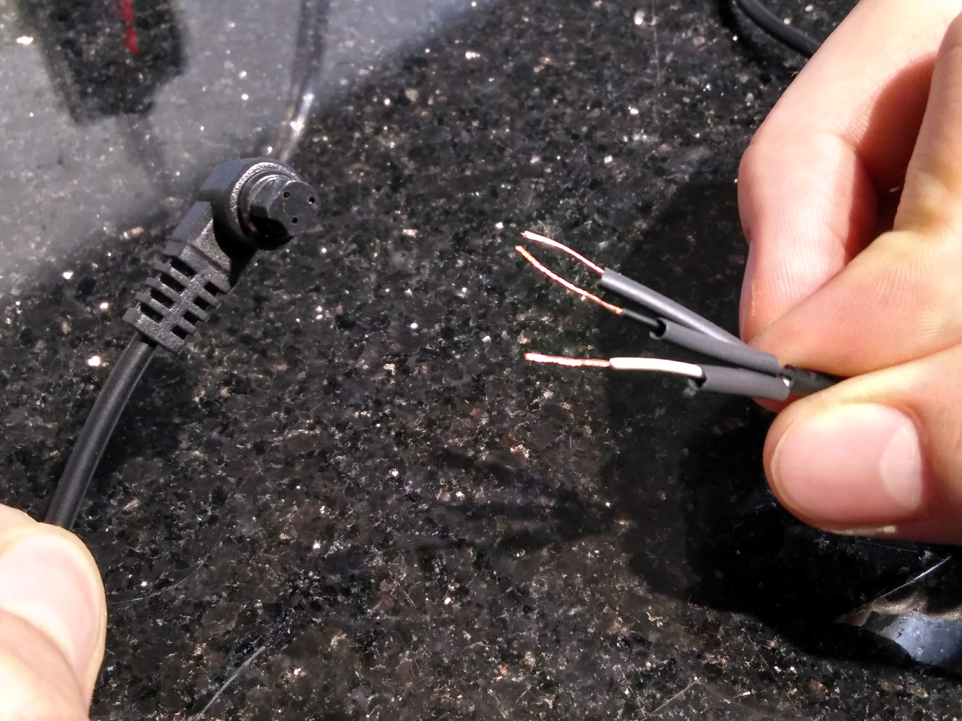
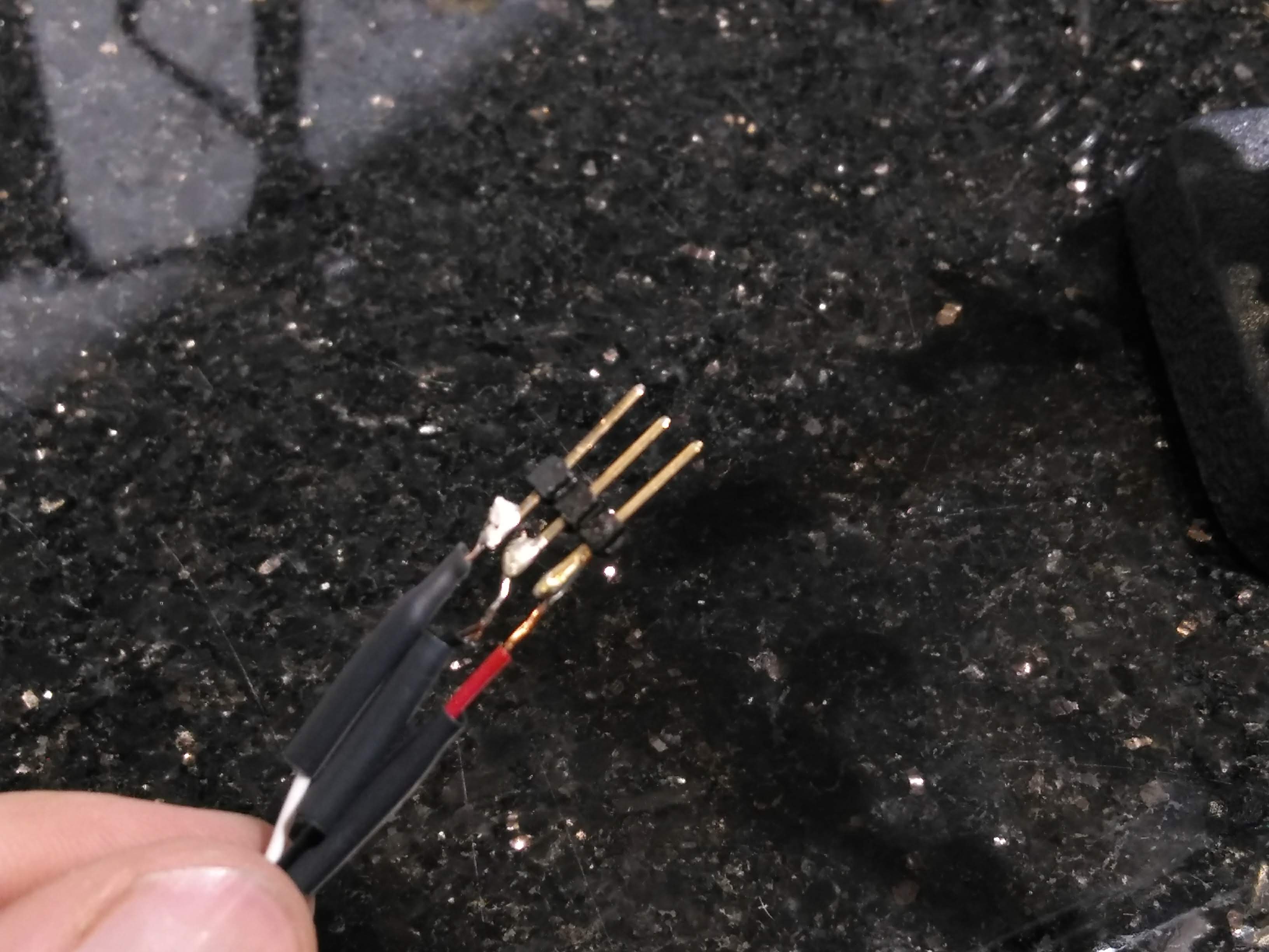
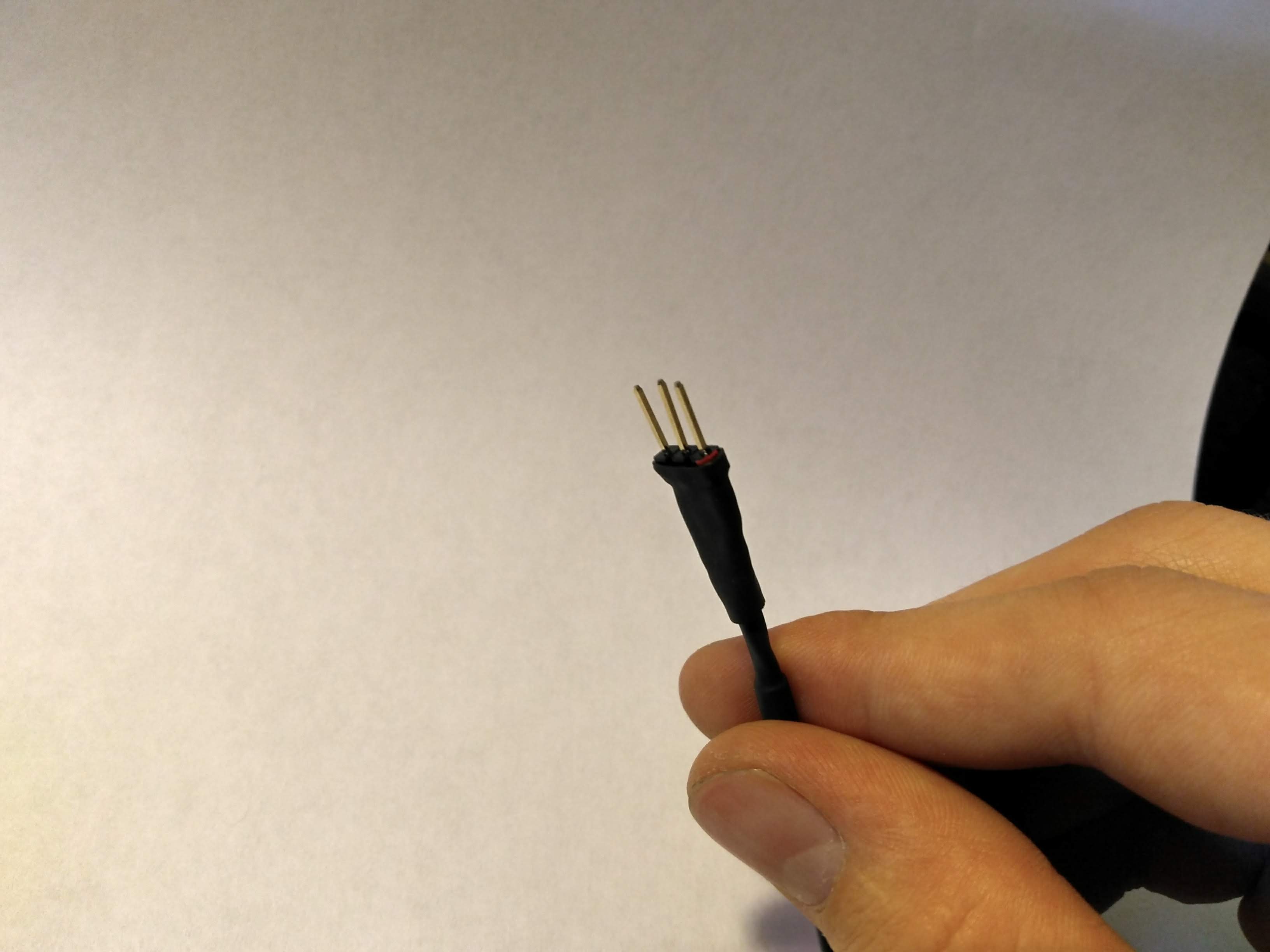
The remote works as follows: when the button is pressed down halfway, the top two metal pieces touch, which shorts the white wire to the black wire, in turn triggering the camera to focus. When the button is pressed all the way, all three metal flaps touch, shorting the white wire to the red wire (as well as the black, but that doesn't matter here), which triggers the camera to take the photo. In order to trigger the camera to take in image in my final device, all I need to do is short those two wires (the red and the white) together on command. For now, I just need to solder a convenient connector to these wires - I'm using a header here as it's easy to plug into a breadboard. I desoldered the wires from the metal flaps in the remote, then I soldered the header to the wires, covered the exposed wire with heat-shrink tubing, and stuck a small piece of red electrical tape on one side of the conector to help with orienting the connector later (this can be seen if you zoom in on the last image below).
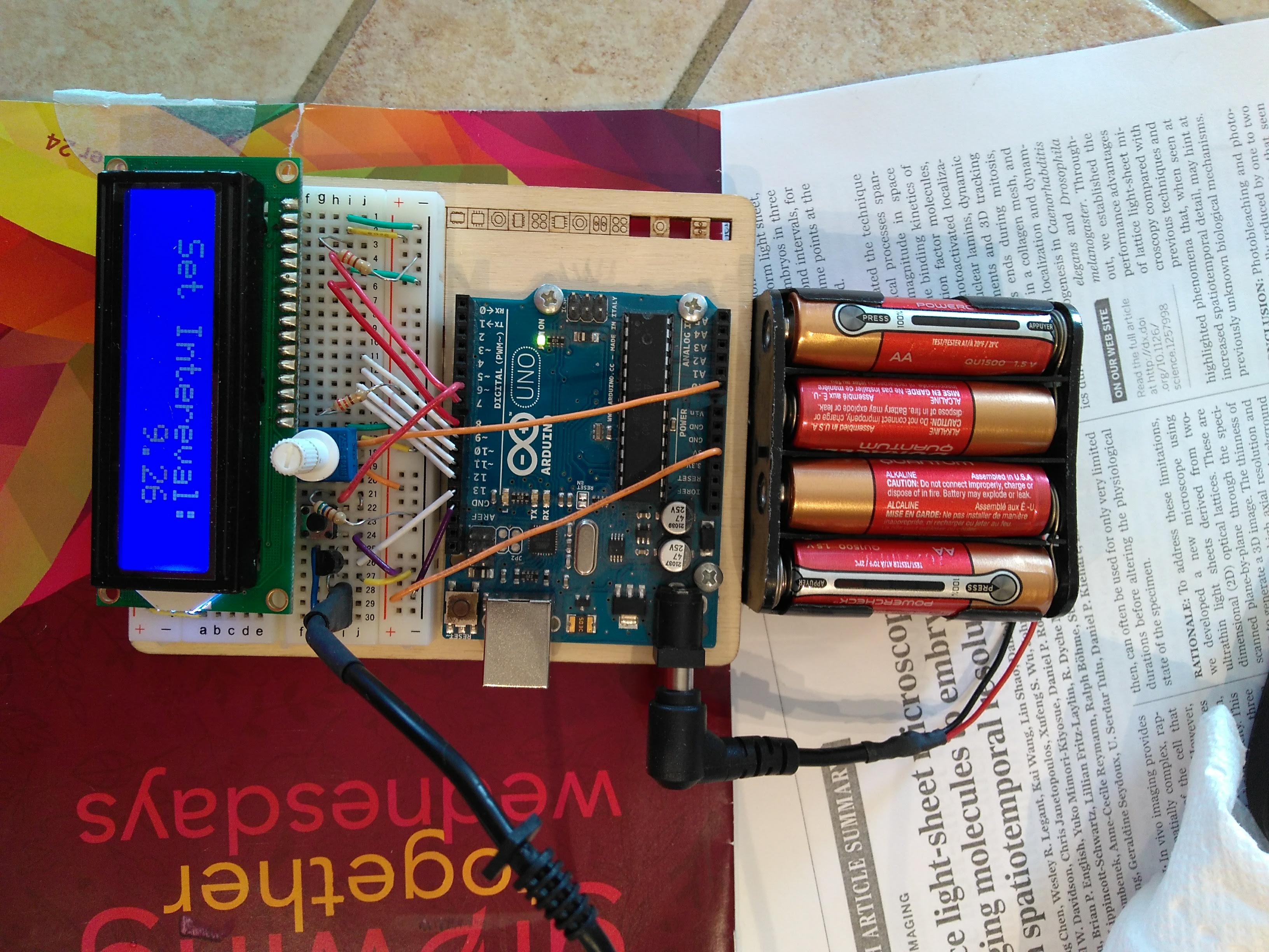
Next, I needed a way to power the Arduino, which requires a 12 volt supply. I found an 8x AA battery holder in my garage, which outputs 12 volts to a 9-volt-battery-like connector. The only connector I had like it was broken, so I had to solder the broken-off wire back on. This required cutting up the plastic cover on the connector, so I fixed this damage with some heat-shrink tubing after solding.
I then soldered the other end of the cable to a 5.5mm coax power connector (what the Arduino accepts) that I scrapped from an old power supply.
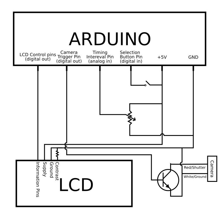
With the soldering done, I could now figure out the circuit for the whole device. It's mostly straightforward, with the input pins on the LCD connected directly to the digital output pins on the Arduino. To trigger the camera, I hooked up the red wire from the trigger cable to the collector on a transistor, the digital output on the Arduino to the base, and the emitter to the white wire and to the Arduino's ground. This way, when the Arduino sends a high signal (which is relative its own ground), the white and red wires are essentially shorted, and the camera is triggered (a relay would normally be used here, but I didn't have one that could be triggered at the low output voltages of the Arduino). The potentiometer is used as a voltage divider, which feeds into the Arduino's analog input, to adjust the timing intereval of the timelapse. I used a simple resistor instead of a potentiometer on the contrast pin of the LCD so that I wouldn't accidentally turn it while trying to adjust the timing intereval.
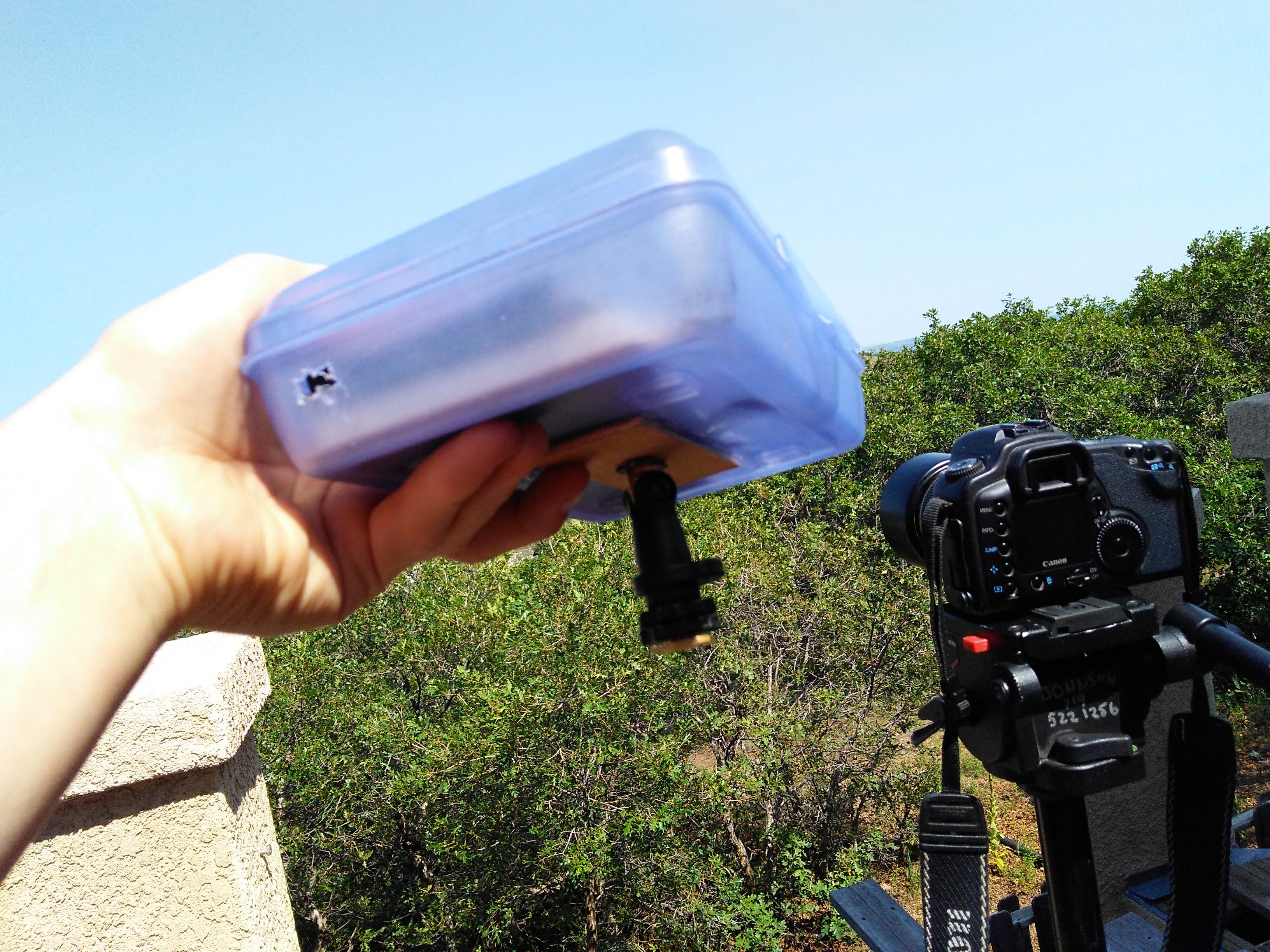
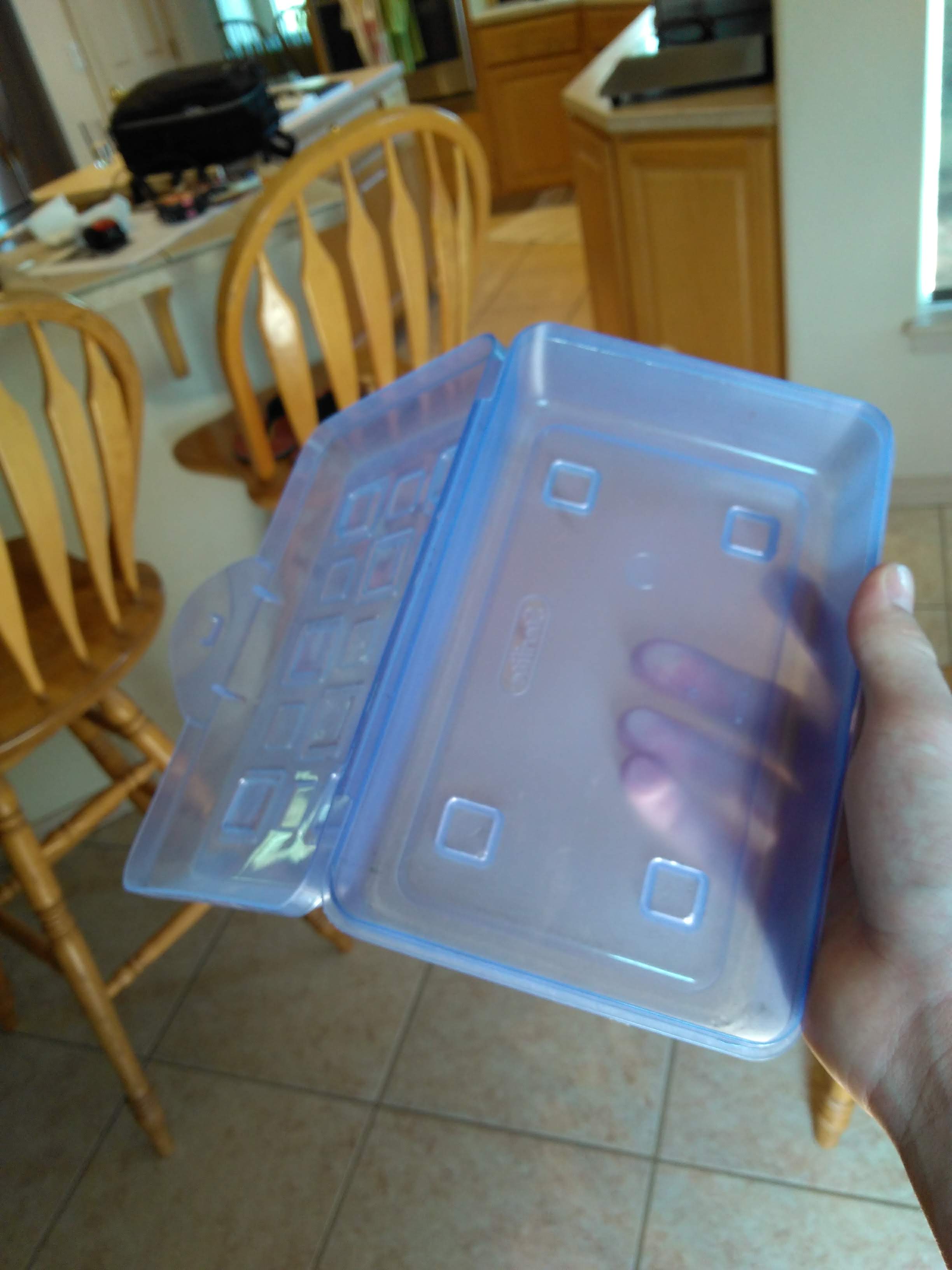
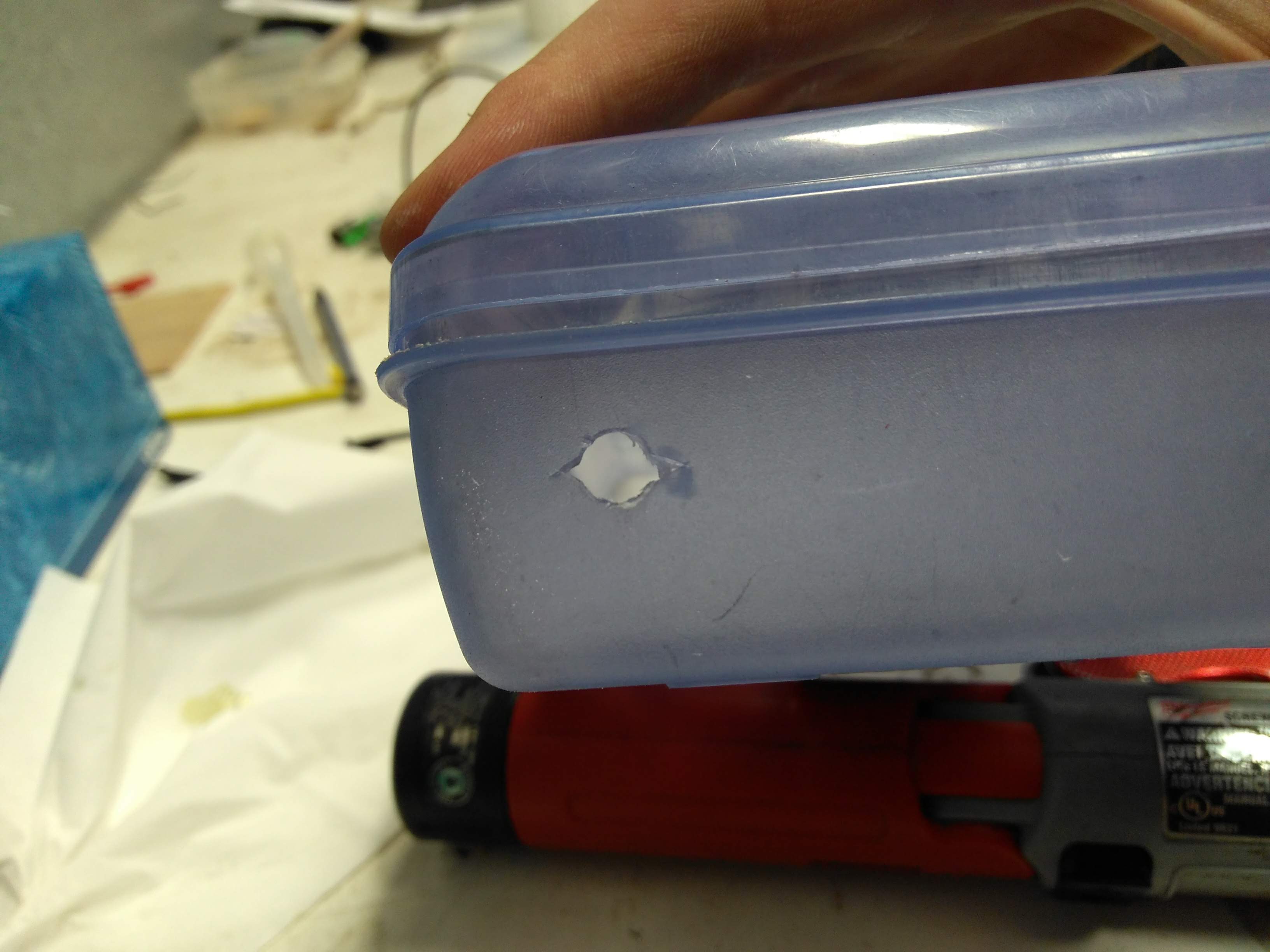
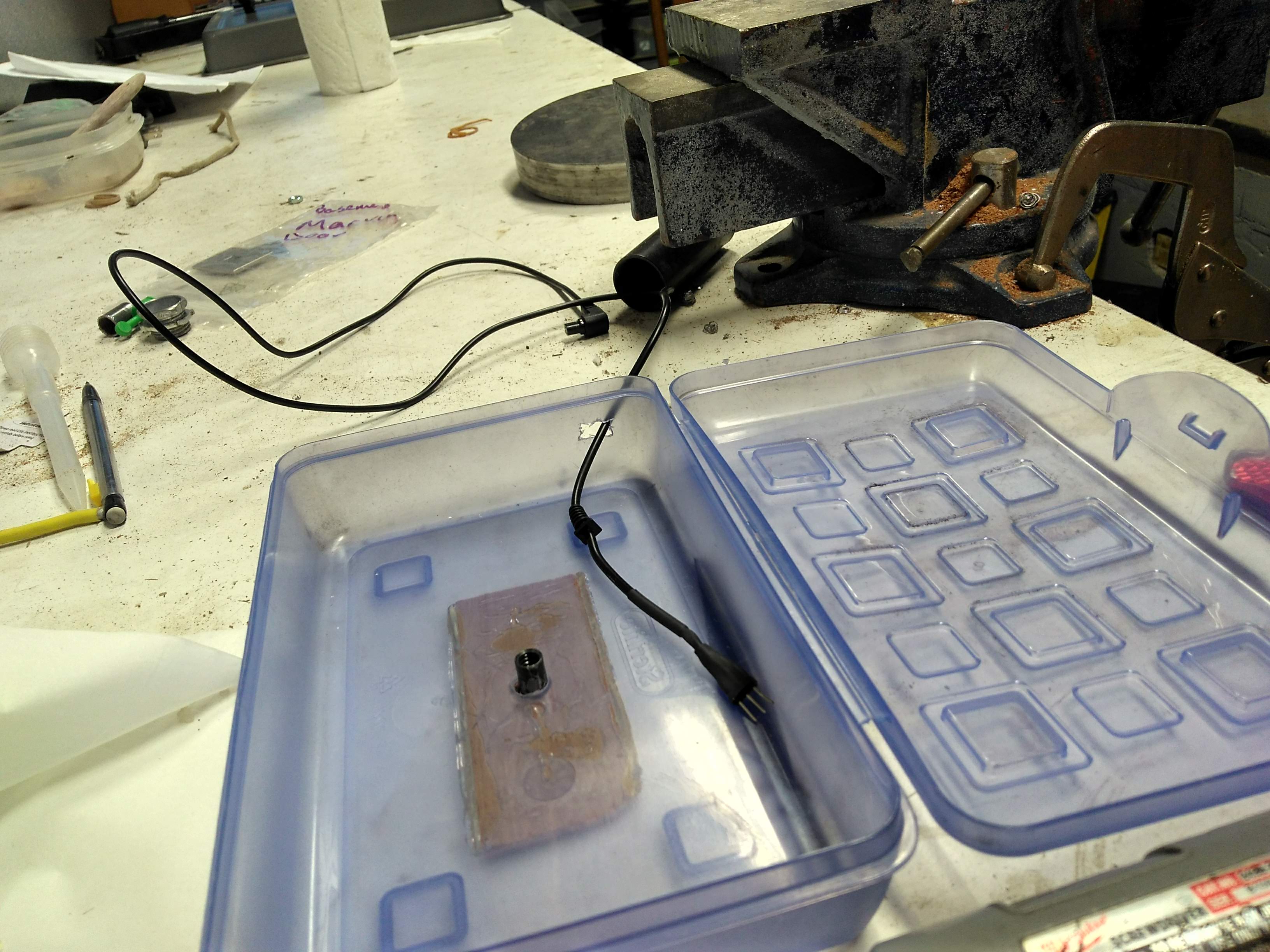
I found an old pencil case to use as a housing for all the electronics. First, I drilled a hole in the side of the case for the camera trigger cable to poke out of when the lid of the case is closed.
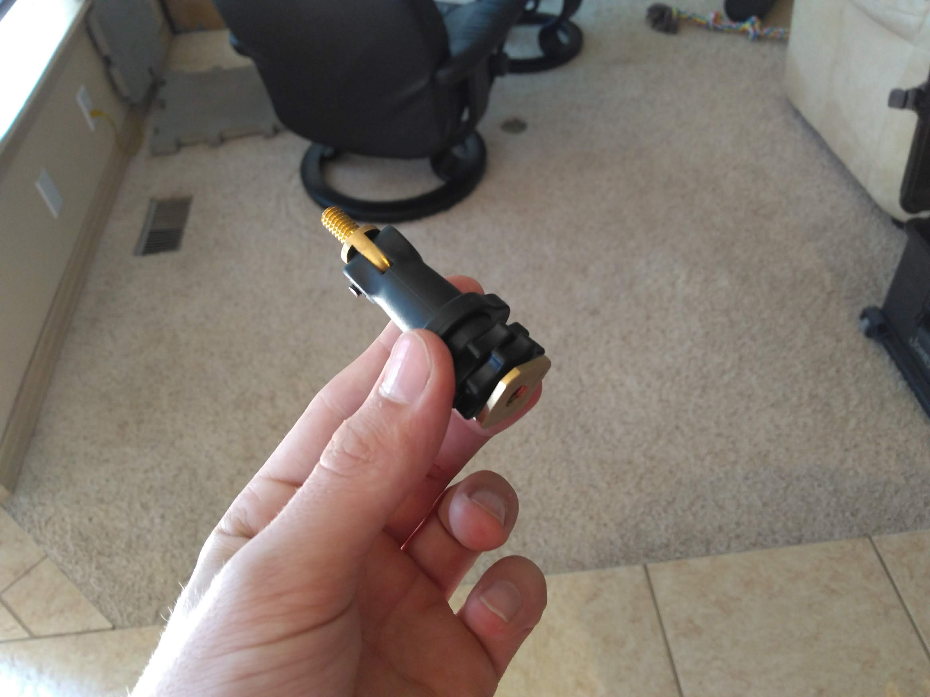
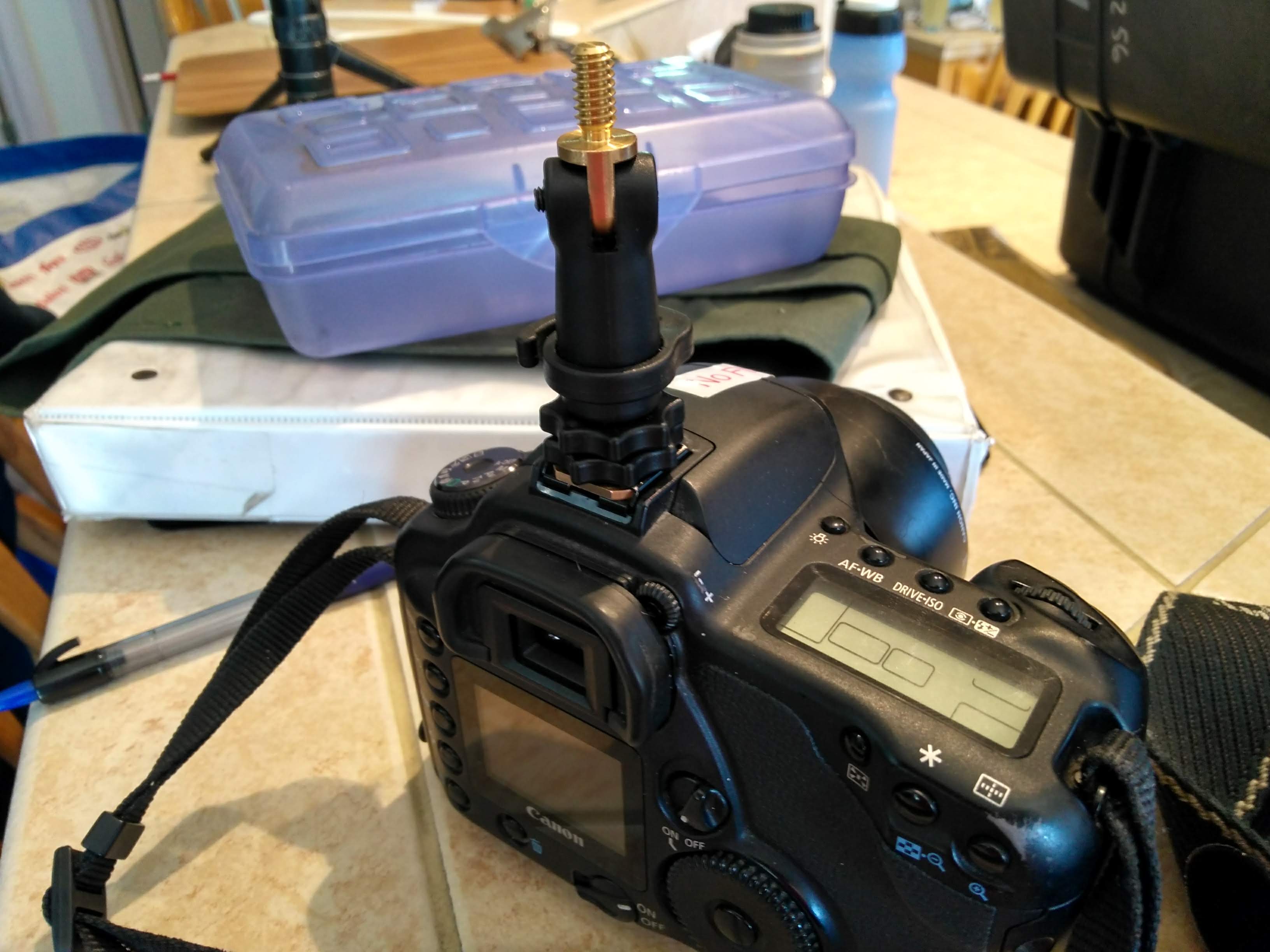
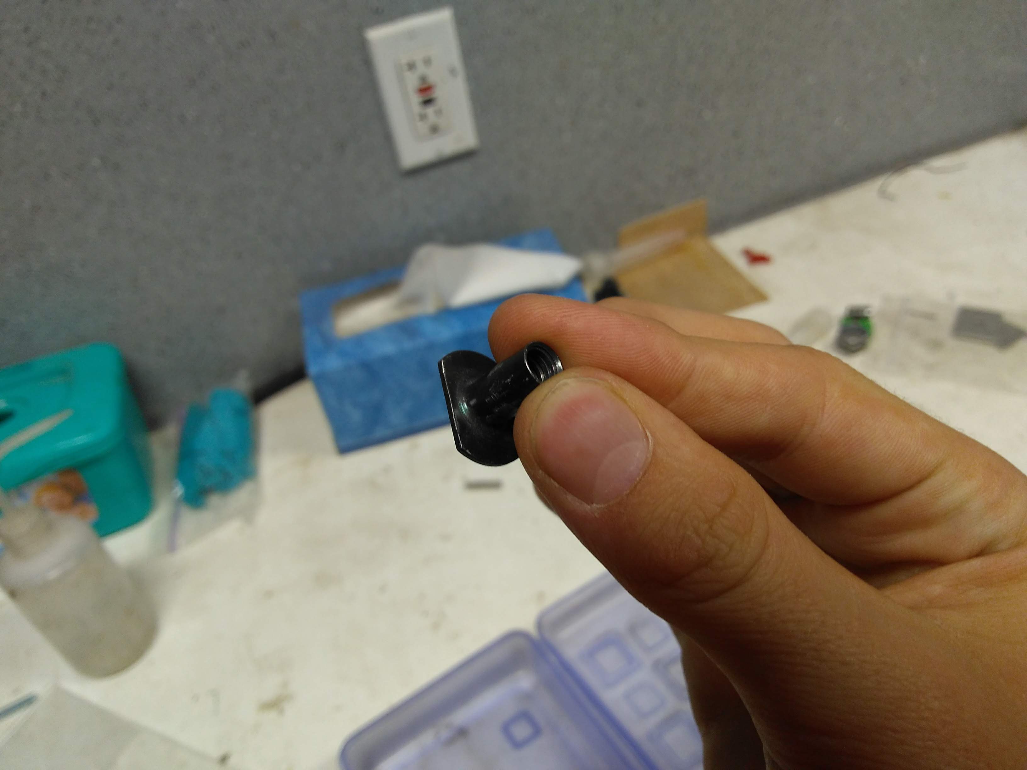
Though the device is technically usuable by now, I also wanted to be able to mount it to the camera. I found a 1/4" screw to standard hot shoe adapter laying around, which I could attach to the top of my camera and mount the pencil case on.
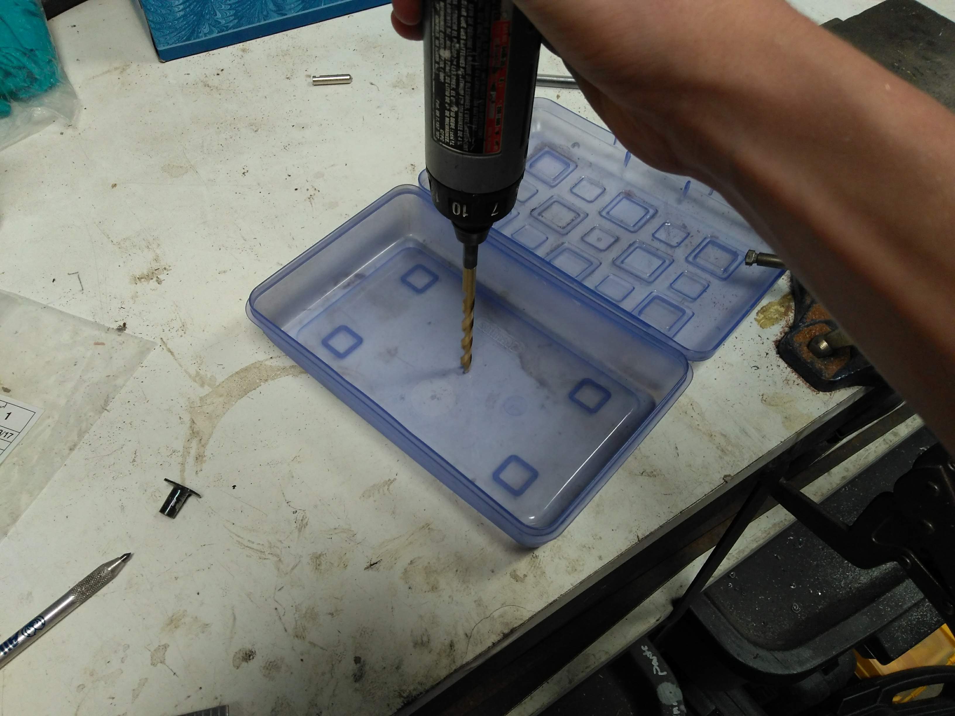
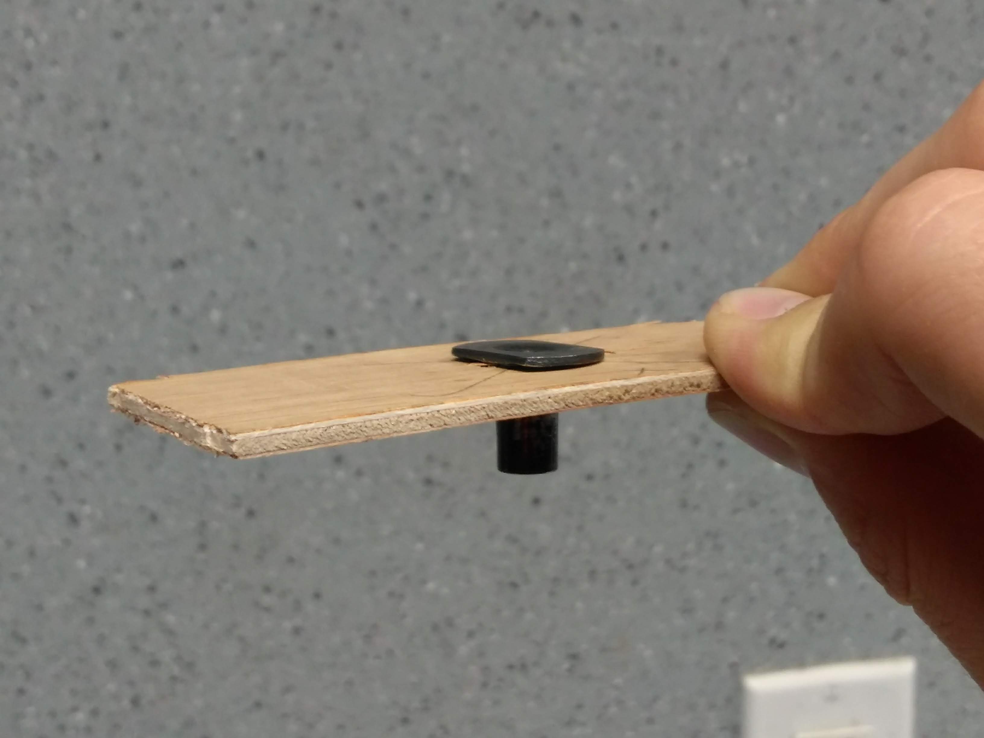
I drilled a hole in the bottom of the pencil case. I then glued a 1/4" threaded T-nut, which I reinforced with a scrap piece of wood, into the hole.
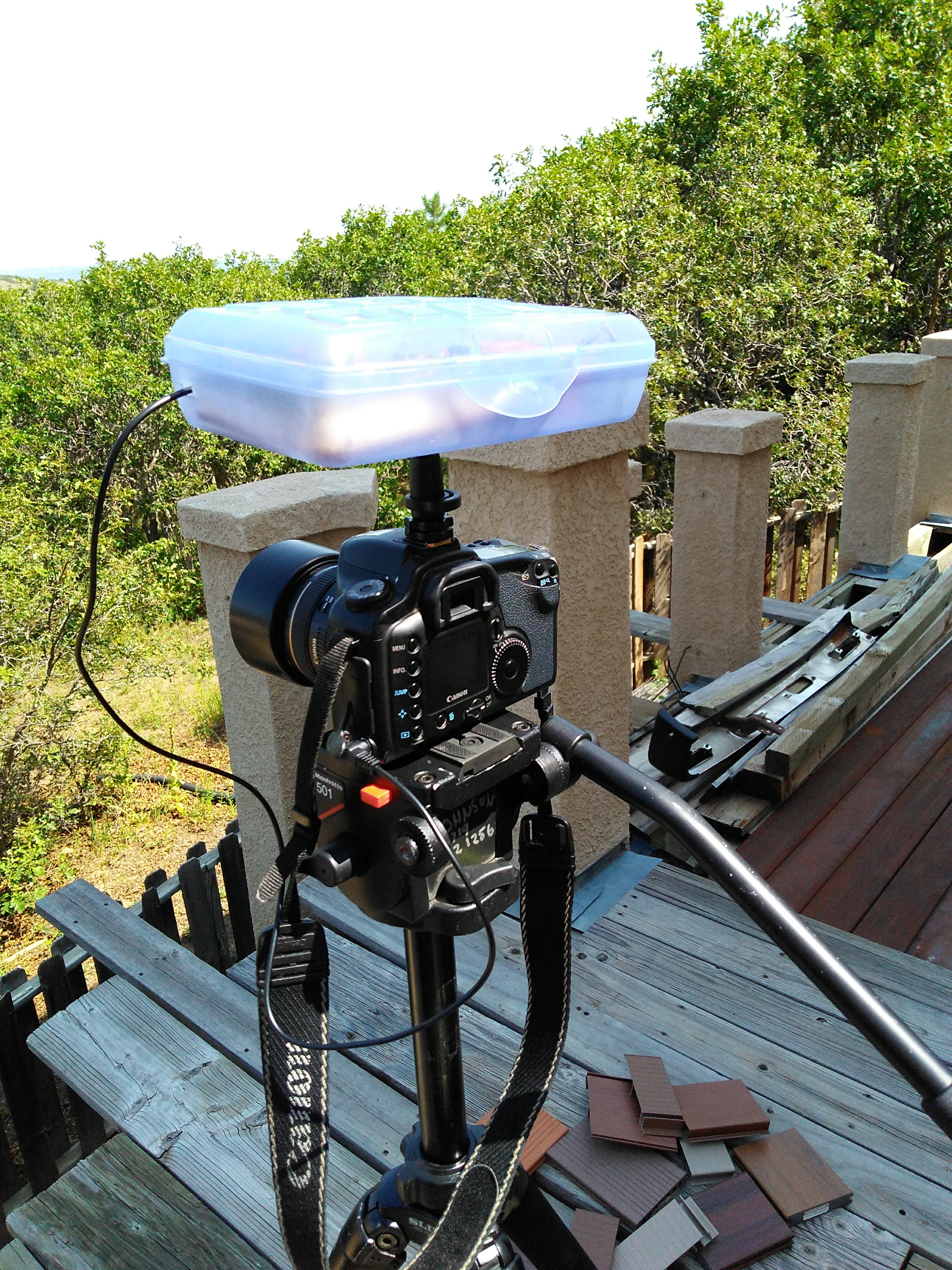
With the case finished, I could place all the components in it, and mount it on a camera.